
Networking 104: Understanding IP Addresses
What Is an IP Address?
An IP address (Internet Protocol address) is a numerical label assigned to every device on a network that uses the Internet Protocol for communication. It serves two primary purposes:
- Identification – Uniquely identifies a device (host) on the network.
- Location addressing – Helps in routing packets from the source to the destination.
When data travels across a network, it's broken into packets. The IP layer ensures each packet is tagged with:
- Source IP (where it came from)
- Destination IP (where it’s going)
This system allows routers and devices to decide the best path for forwarding each packet. Importantly, IP doesn’t care if a packet arrives or not it just handles addressing and routing. Reliability is the job of other protocols (like TCP).
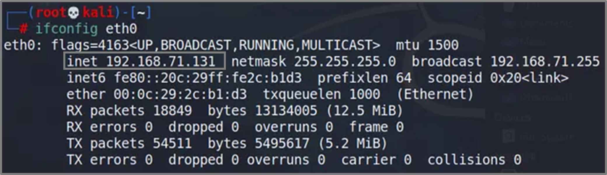
Using ifconfig: Checking IP address in Linux.
ISP (Internet Service Provider)
An ISP (Internet Service Provider) is a company or organization that provides access to the internet. It connects your home or business network to the broader internet infrastructure through technologies like fiber, DSL, cable, or wireless. ISPs assign public IP addresses, manage data routing, and often provide DNS services. They act as the gateway between your local network and the global internet, ensuring your requests reach external servers and responses return to you correctly. Without an ISP, you wouldn't be able to access websites, stream content, or communicate online.
Why Was IP Needed?
Before the IP protocol, there was no standardized way for machines across different networks to identify each other and communicate. IP was developed to:
- Enable communication across heterogeneous systems
- Support scalability beyond local networks
- Establish a uniform addressing scheme
- Provide network-layer packet delivery
With the internet growing from a few hosts to billions of devices, IP became the backbone of modern digital communication.
Types of IP: IPv4 vs.IPv6
| Feature | IPv4 | IPv6 |
| Full Name | Internet Protocol version 4 | Internet Protocol version 6 |
| Address Format | 32-bit numeric, written in decimal | 128-bit hexadecimal, written in colon-separated blocks |
| Notation Example | 192.168.1.1 | 2001:0db8:85a3:0000:0000:8a2e:0370:7334 |
| Address Length | 4 numbers (0–255), separated by dots | 8 blocks of 4 hex digits, separated by colons |
| Address Space | ~4.3 billion addresses | ~340 undecillion addresses |
| Header Complexity | Simpler | More fields, supports options like QoS, flow labels |
| Security (native) | Not built-in | IPSec is mandatory |
| Broadcast Support | Yes | No (uses multicast/anycast instead) |
| Security (native) | Widely used, but running out of space | Adoption growing, especially in modern systems |
IPv4 vs. IPv6: Why Two Versions?
IPv4 was the first widely deployed version of the Internet Protocol, but with only about 4.3 billion unique addresses, it couldn’t scale to support the explosive growth of devices. To address this, IPv6 was developed, offering a virtually unlimited address space and modern enhancements such as built-in security, automatic configuration, and improved mobility support.
IPv4 and IPv6 are not directly interoperable; they use completely different addressing formats and packet structures. Some dual-stack systems can handle both, but in general, IPv6 is not backward compatible with IPv4.
IPv4 is simpler, more widespread, and better supported by legacy systems. IPv6, while more complex, enables true end-to-end connectivity, eliminates NAT in many cases, and is better suited for the future of networking.
Breaking Down an IP Address (IPv4)
An IPv4 address is a 32-bit binary number, written in human-readable decimal form as four “octets” separated by dots. Each octet represents 8 bits, making a total of 32 bits:
Example: 192.168.1.1
IPv4 = 32 bits → 4 octets
What Is an Octet?
An octet is simply 8 bits (1 byte). Each octet can represent a number from:
22 (1) to 28 – 1 = 255
So each octet can hold values from 0 to 255, giving 256 total possible values per octet.
Example in Binary:
Decimal: 192.168.1.1
Binary: 11000000.10101000.00000001.00000001
Why 2⁸?
Each bit has 2 possible values: 0 or 1. So:
- 1 bit → 2 values
- 2 bits → 2² = 4 values
- 3 bits → 2³ = 8 values ...
- 8 bits (an octet) → 2⁸ = 256 values (from 0 to 255)
Here’s a complete breakdown of IP address classes with binary prefix, address ranges, bit distribution, and purpose plus a short description for each.
IPv4 Address Classes (A–E)
| Class | Starting Bits | Address Range |
Network Bits | Host Bits | Number of Networks |
Hosts per Network |
Usage |
| A | 0 | 0.0.0.0–127.255.255.255 | 8 bits | 24 bits | 128 (0–127) | ~16 million | Very large networks |
| B | 10 | 128.0.0.0– 191.255.255.255 | 16 bits | 16 bits | 16,384 | ~65,000 | Medium-sized networks |
| C | 110 | 192.0.0.0 – 223.255.255.255 | 24 bits | 8 bits | ~2 million | 254 | Small networks Multicast |
| D | 1110 | 224.0.0.0 – 239.255.255.255 | — | — | — | — | Multicast |
| E | 1111 | 240.0.0.0 – 255.255.255.255 | — | — | — | — | Experimental |
- Class A:
- Starts with binary 0
- Reserved for large organizations or ISPs
- First octet: 1–126 (127 is loopback)
- Class B:
- Starts with binary 10
- Balanced between network and host bits
- Often used by universities, medium orgs
- Class C:
- Starts with binary 110
- Supports many small networks
- Default choice for small businesses
- Class D:
- Starts with binary 1110
- Reserved for multicast (1-to-many) communication
- Class E:
- Starts with binary 1111
- Reserved for research, experimental use only
- Starts with binary 0
- Reserved for large organizations or ISPs
- First octet: 1–126 (127 is loopback)
- Starts with binary 10
- Balanced between network and host bits
- Often used by universities, medium orgs
- Starts with binary 110
- Supports many small networks
- Default choice for small businesses
- Starts with binary 1110
- Reserved for multicast (1-to-many) communication
- Starts with binary 1111
- Reserved for research, experimental use only
Each IP address is typically divided into:
- Network part: Identifies the network
- Host part: Identifies the device on that network
Depending on the subnet mask, the bits are split to define what portion is network vs. host.
For example, with 192.168.1.1/24:
- /24 means the first 24 bits are for the network (192.168.1)
- Last 8 bits (.1) are for the host
Subnet Masks for IP Classes
A subnet mask defines how many bits in an IP are used for network portion vs. the host portion. The natural mask (also called default subnet mask) refers to the default bit boundaries for each IP class when no custom subnetting is applied.
Why Subnet?
- Reduce network congestion
- Improve security and organization
- Avoid wasting IP addresses
CIDR Notation
CIDR (Classless Inter-Domain Routing) uses the /x suffix to indicate how many bits are for the network.
Example: 192.168.10.0/28 → 16 total IPs, 14 usable
Default (Natural) Subnet Masks by Class
| Class | Default Subnet Mask | CIDR Notation | Network Bits | Host Bits | Max Hosts per Network |
| A | 255.0.0.0 | /8 | 8 | 24 | 16,777,214 |
| B | 255.255.0.0 | /16 | 16 | 16 | 65,534 |
| C | 255.255.255.0 | /24 | 24 | 8 | 254 |
Formula for usable hosts: 2^host bits − 2 (network + broadcast reserved)
What Does a Subnet Mask Do?
- Separates the IP address into network and host portions.
- Helps routers and devices determine:
- Is the destination device local? (same subnet)
- Or remote? (needs to go through a gateway/router)
- Class A
- IP: 10.0.0.5
- Mask: 255.0.0.0 → Only first octet is the network (10.x.x.x)
- Class B
- IP: 172.16.34.10
- Mask: 255.255.0.0 → First two octets define the network
- Class C
- IP: 192.168.1.100
- Mask: 255.255.255.0 → First three octets define the network
- Is the destination device local? (same subnet)
- Or remote? (needs to go through a gateway/router)
- IP: 10.0.0.5
- Mask: 255.0.0.0 → Only first octet is the network (10.x.x.x)
- IP: 172.16.34.10
- Mask: 255.255.0.0 → First two octets define the network
- IP: 192.168.1.100
- Mask: 255.255.255.0 → First three octets define the network
Custom Subnetting: Making Networks Fit Your Needs
Subnetting is the process of dividing a large network into smaller, more manageable pieces called subnets. Instead of sticking to the default class sizes (like Class C’s 254 hosts), you can create custom subnet sizes to better match the number of devices you need to support.
How It Works
Every subnet mask tells us how many bits are used for the network and how many for hosts. When we borrow bits from the host part, we create more subnets but get fewer hosts per subnet.
Example: Subnetting 192.168.1.0
Default mask: /24 → 255.255.255.0
- Hosts per subnet: 2⁸ − 2 = 254
Custom subnet: /26 → 255.255.255.192
- 2 bits borrowed → 2² = 4 subnets
- Hosts per subnet: 2⁶ − 2 = 62
Now your single /24 network becomes four smaller ones:
| Subnet | Usable IPs |
| 192.168.1.0/26 | 192.168.1.1 – .62 |
| 192.168.1.64/26 | 192.168.1.65 – .126 |
| 192.168.1.128/26 | 192.168.1.129 – .190 |
| 192.168.1.192/26 | 192.168.1.193 – .254 |
NAT (Network Address Translation)
NAT (Network Address Translation) allows devices using private IP addresses to communicate over the internet. Since private IPs aren’t routable on public networks, NAT translates them into a single public IP usually provided by the ISP.
This means multiple devices in a home or office can share one public IP address, making efficient use of limited IPv4 space. NAT keeps track of which internal device sent which request so that replies from the internet are routed back correctly. Without NAT, private IPs couldn't reach public servers.
Public vs. Private IP Addresses
IP addresses are divided into two broad categories: public (globally routable) and private (used inside local networks). Devices on a private network need a public IP to communicate over the internet usually handled via NAT (Network Address Translation).
Public: Globally unique IPs assigned by your ISP, visible on the internet.
Private: IPs reserved for local use within LANs, not routable on the public internet.
Special IPv4 Address Ranges
| IP Range | Purpose | Subnet Mask | Description |
| 10.0.0.0 – 10.255.255.255 | Private Network | 255.0.0.0(/8) | Used for large internal networks. Not routable on the public internet. |
| 172.16.0.0 – 172.31.255.255 | Private Network | 255.240.0.0(/12) | Medium-sized private networks (Class B range). |
| 192.168.0.0 – 192.168.255.255 | Private Network | 255.255.0.0(/16) | Common for home and small office networks. |
| 127.0.0.0 – 127.255.255.255 | Loopback | 255.0.0.0(/8) | Used to test local system networking (e.g., 127.0.0.1 = localhost). |
| 169.254.0.0 – 169.254.255.255 | Link-Local | 255.255.0.0(/16) | Auto-assigned if DHCP fails. Only used for communication within local link. |
DHCP (Dynamic Host Configuration Protocol)
DHCP (Dynamic Host Configuration Protocol) is used to automatically assign IP addresses and network settings to devices on a network. Instead of manually configuring each device, DHCP handles it centrally providing an IP address, subnet mask, default gateway, and DNS server information.
When a device joins the network, it sends a DHCP discovery request. The first DHCP server to respond offers the configuration. This can be a router, a computer, or any system running DHCP services.
However, DHCP lacks authentication. There's no built-in mechanism to verify the identity of the DHCP server or the client. This makes it vulnerable to spoofing attacks where a rogue DHCP server can assign incorrect settings to mislead or intercept traffic.
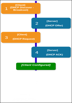
DHCP Flow (DORA process)
- Client → DHCP Discover (Broadcast)
- Client sends a broadcast to find available DHCP servers.
- Server → DHCP Offer
- a. One or more servers respond with an available IP and configuration options.
- Client → DHCP Request
- Client requests the offered IP from a specific DHCP server (based on the offer it chooses).
- Server → DHCP Acknowledgment (ACK)
- Server confirms lease of the IP and provides full network configuration.
- DHCP NAK: If the server denies the request (e.g., IP conflict), it sends a negative acknowledgment.
- Lease Renewal: Client will later re-request the lease before it expires (handled via unicast, not broadcast).
- DHCP Decline: If the client detects that the offered IP is already in use, it may send a decline message.
- Client sends a broadcast to find available DHCP servers.
- a. One or more servers respond with an available IP and configuration options.
- Client requests the offered IP from a specific DHCP server (based on the offer it chooses).
- Server confirms lease of the IP and provides full network configuration.
- DHCP NAK: If the server denies the request (e.g., IP conflict), it sends a negative acknowledgment.
- Lease Renewal: Client will later re-request the lease before it expires (handled via unicast, not broadcast).
- DHCP Decline: If the client detects that the offered IP is already in use, it may send a decline message.
ICMP (Internet Control Message Protocol)
ICMP (Internet Control Message Protocol) is used by network devices, especially routers, to send error messages and operational feedback about IP packet processing. It’s not used for data transfer only for diagnostics and error reporting.
Key Functions of ICMP
- Informs the source IP when delivery of packets fails (e.g., destination unreachable, time exceeded).
- Helps identify problems like routing failures or unreachable hosts.
- Operates at the Network Layer (Layer 3) alongside IP.
ICMP and Traceroute
- Traceroute uses ICMP to map the path packets take across an IP network.
- It sends packets with incrementing TTL (Time to Live) values.
- Each router that decrements the TTL to 0 sends back a Time Exceeded ICMP message.
- These replies reveal the IP address of each hop along the route and the time taken to reach them.
This allows users to trace where delays or failures occur in the network path between source and destination.
Conclusion
IP addressing is the backbone of network communication. It allows devices to be uniquely identified, ensures data reaches the correct destination, and supports everything from small private networks to the global internet. Whether through static configuration or dynamic assignment, and whether using IPv4 or IPv6, the principles behind IP help maintain order and reliability in digital communication. A solid grasp of these concepts is essential for anyone working with or securing networked systems.

Address:
601, park plaza business center, S No. 296/2, Porwal Rd, Lohegaon, Pune, Maharashtra 411047
Phone: 91 8454095561
Email: [email protected]
GET IN TOUCH:
©Copyright 2024 Unoacademy Labs LLP